

Introduction
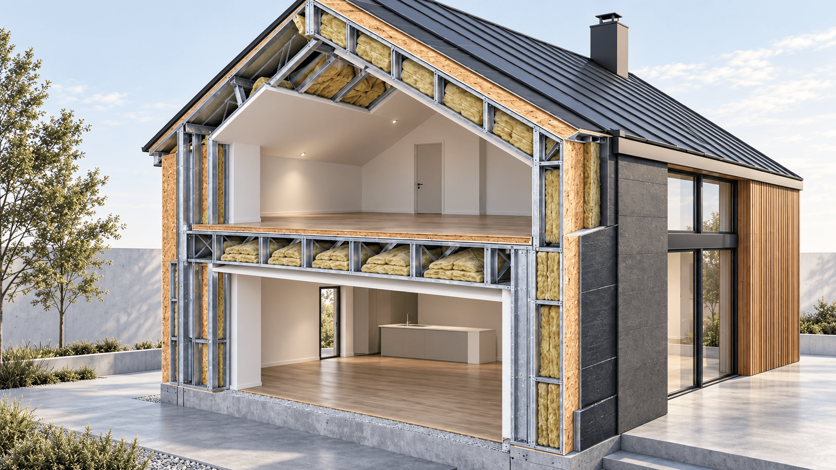
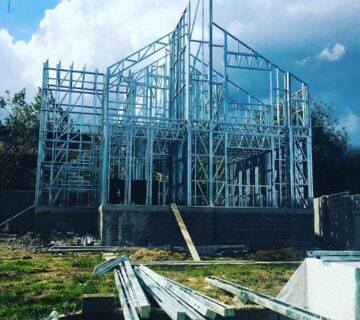
The LSF (Light Steel Frame) system is an industrialized construction method in which cold-formed steel sections, following engineering design and precise manufacturing, form the main structural components of the building’s walls, floors, and roof.
However, an LSF building consists of much more than its steel frame. The final performance and quality of the building result from the coordinated operation of the structural system, connections, sheathing and finishing layers, thermal and acoustic insulation, moisture-control layers, façade system, and roof covering.
For this reason, selecting the appropriate covering and assembly system in LSF construction is an integral part of the engineering process, and a single fixed configuration cannot be applied to every project.
Climate conditions, building occupancy, number of stories, architectural design, environmental humidity, fire-resistance requirements, acoustic performance, energy efficiency, and the selected façade system all influence the choice of appropriate materials and layers.
1. Floor Systems in LSF Construction
Floor systems in LSF buildings are typically supported by lightweight steel floor joists.
In addition to carrying and transferring structural loads, the floor assembly must provide a suitable substrate for the finished flooring and, particularly in multi-story buildings, help control sound transmission and vibration.
Recommended Floor Assembly – From Top to Bottom
1. Final Floor Finish
Depending on the architectural requirements, materials such as ceramic tiles, natural stone, parquet, laminate, or other suitable flooring systems may be used.
2. Underlayment and Acoustic-Control Layer
This layer is selected according to the final flooring material and may contribute significantly to reducing impact sound transmission.
Its thickness is not fixed and should be selected according to the chosen flooring system.
3. Structural Floor Sheathing
Structural OSB, plywood, cement board, or suitable cement particle boards may be used in this layer.
For preliminary design purposes, thicknesses in the approximate range of 18 to 22 mm may be considered. However, the final thickness depends on joist spacing, structural loads, panel specifications, and engineering calculations.
4. LSF Floor Joists
The floor joists are the main load-bearing members of the floor structure.
Their dimensions, steel thickness, and spacing must be determined according to structural calculations.
5. Insulation Between Joists
Rock wool or glass wool insulation may be installed between the floor joists.
Depending on the project, thicknesses of approximately 50 to 100 mm or more may be considered.
In addition to improving thermal performance, this layer can contribute to reducing sound transmission between floors.
6. Ceiling Subframe for the Lower Floor
A suitable subframe is installed below the floor joists to support the internal ceiling finish.
7. Gypsum Board Ceiling
Gypsum boards with approximate thicknesses of 12.5 or 15 mm may be used for the ceiling below.
Where additional fire-resistance or acoustic performance is required, the type or number of gypsum board layers may be modified.
Important Note About LSF Floors
One common construction mistake is to consider an LSF floor simply as “OSB installed over steel joists.”
A properly designed floor should be treated as a multi-layer assembly capable of addressing structural strength, vibration, impact noise, airborne sound transmission, and fire-resistance requirements.
2. External Wall Systems in LSF Construction
The external wall is one of the most important components of an LSF building because it must simultaneously address several performance requirements:
Thermal performance, sound insulation, wind, rain, moisture, fire resistance, and façade support.
Therefore, the correct sequence and design of the wall layers are extremely important.
Recommended Wall Assembly – From Inside to Outside
1. Interior Gypsum Board
Gypsum boards with approximate thicknesses of 12.5 to 15 mm may typically be used.
Depending on the intended use of the space, standard boards, moisture-resistant boards, or systems with specific fire-resistance ratings may be selected.
2. Service Cavity
Where required, a dedicated cavity may be provided for electrical and mechanical services.
This arrangement can reduce interference between building services and the main structural components of the wall.
3. LSF Steel Studs
Steel studs form the primary structural members of the wall.
Their dimensions, thickness, and spacing are determined according to structural design requirements.
4. Thermal and Acoustic Insulation
The cavity between the studs provides space for insulation.
Rock wool is one suitable option, and depending on wall depth and thermal calculations, approximate thicknesses ranging from 50 to 150 mm may be considered.
5. Sheathing Board
On the exterior side of the studs, structural OSB or other suitable sheathing boards may be used depending on the selected wall system.
For preliminary design, approximate thicknesses of 9 to 12 mm may be considered.
However, if the sheathing forms part of the building’s lateral load-resisting system, the board type, thickness, fasteners, and fastening pattern must be specified precisely by the structural engineer.
6. Weather-Resistive Barrier
After the sheathing layer, an appropriate WRB (Weather-Resistive Barrier) or building membrane can help prevent water penetration into the wall assembly while allowing appropriate moisture and vapor management according to the building-envelope design.
7. Continuous Thermal Insulation
Steel has relatively high thermal conductivity, and steel studs may create thermal bridges through the building envelope.
For projects with higher energy-performance requirements, continuous insulation outside the steel studs may therefore be considered.
Depending on project calculations, thicknesses of approximately 20 to 50 mm or more may be used.
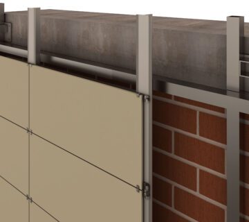
8. Façade Substructure
The façade support and substructure system is designed according to the selected exterior finish.
9. Final Façade
One of the advantages of LSF construction is its architectural flexibility in terms of façade selection.
With proper engineering, materials such as the following can be used:
Natural stone, brick, fiber cement panels, metal sheets, composite panels, HPL panels, engineered wood, and various types of ventilated or dry façade systems.
When heavy façade materials are used, their weight and load-transfer mechanism must be considered from the early stages of structural and connection design.
3. OSB or Fiber Cement Board?
One common question in LSF construction is whether OSB or fiber cement board should be used.
The answer is that these two materials are not necessarily direct substitutes for each other.
OSB can be used as structural sheathing in certain systems and, when properly designed, may also contribute to the building’s lateral load-resisting system.
In contrast, fiber cement board is a cement-based panel that is widely used in applications requiring suitable resistance to moisture and environmental exposure.
For fiber cement boards, thicknesses in the approximate range of 8 to 12 mm are common in certain applications. However, the exact product and thickness should always be selected based on the manufacturer’s technical documentation and the specific construction system.
Therefore, the correct selection should not be based simply on the question, “Which one is better?”
The first question should be:
What function is the board expected to perform within the wall assembly?
4. Pitched Roof Systems in LSF Construction
Pitched roofs are one of the applications particularly well suited to LSF construction.
The ability to manufacture accurate trusses and rafters, reduce roof weight, and create a wide range of architectural forms makes the system suitable for villas, residential buildings, schools, and many other low-rise buildings.
Recommended Roof Assembly – From Outside to Inside
1. Final Roof Covering
Possible materials include metal roofing sheets, standing seam systems, tile-profile metal sheets, shingles, roof tiles, and other suitable roof coverings.
2. Roof Covering Substructure
The type of supporting substructure depends on the selected roofing system.
3. Waterproofing Layer or Membrane
This layer plays an important role in controlling water and moisture penetration.
4. Roof Sheathing
Structural OSB or other approved and suitable boards may be used as roof sheathing.
For preliminary design purposes, thicknesses in the approximate range of 11 to 18 mm may be considered.
The final thickness, however, must be selected according to rafter spacing, snow loads, wind loads, and board specifications.
5. LSF Trusses or Rafters
These are the main load-bearing members of the roof structure.
They are designed according to roof span, roof slope, snow load, wind load, and other relevant design loads.
6. Thermal and Acoustic Insulation
Rock wool or other suitable insulation materials may be installed between structural members.
Approximate thicknesses of 50 to 150 mm or more may be considered depending on thermal calculations and local climate conditions.
7. Service Cavity or Internal Substructure
Where necessary, a service cavity or supporting system can be installed for utilities and interior ceiling finishes.
8. Interior Gypsum Board Ceiling
Gypsum boards with approximate thicknesses of 12.5 to 15 mm may typically be considered.
Where increased fire resistance is required, multi-layer systems or specific fire-rated boards may be selected.
5. Three Simplified Recommended Assemblies
LSF Floor
Floor finish → acoustic layer / underlayment → 18–22 mm structural sheathing → LSF floor joists → 50–100 mm rock wool or according to engineering calculations → ceiling substructure → 12.5–15 mm gypsum board
External LSF Wall
12.5–15 mm gypsum board → optional service cavity → LSF studs + 50–150 mm rock wool → approximately 9–12 mm sheathing → WRB → continuous insulation according to thermal calculations → façade substructure → final façade
LSF Pitched Roof
Final roof covering → supporting substructure → membrane → approximately 11–18 mm roof sheathing → LSF truss/rafter + thermal insulation → internal substructure → 12.5–15 mm gypsum board
6. An Important Principle: Greater Thickness Does Not Always Mean Better Performance
In LSF building design, overall quality should not be evaluated solely by the thickness of the OSB, the amount of rock wool, or the number of gypsum board layers.
The actual performance of the building depends on how effectively the entire assembly works together.
For example, installing a large amount of insulation between steel studs without addressing thermal bridging does not necessarily provide the best thermal performance.
Similarly, increasing the number of gypsum board layers without using a tested or properly engineered assembly does not automatically guarantee a specific fire-resistance rating.
Even high-quality boards and insulation materials cannot provide the expected performance if connections, joints, membranes, and waterproofing details are poorly executed.
7. The Importance of Integrated Design in LSF Buildings
The actual quality of an LSF building results from a continuous and interconnected process:
Engineering design → precision manufacturing → quality control → correct structural installation → selection of covering systems → insulation → moisture management → façade and roof installation → final inspection
For this reason, comparing two LSF buildings solely on the basis of the price per kilogram of steel is not an appropriate way to compare their overall quality.
Two projects may appear visually similar while performing very differently because of differences in engineering design, manufacturing quality, covering systems, insulation, thermal-bridge control, and construction details.
Conclusion
LSF should not be regarded merely as a lightweight steel structural frame.
LSF is a complete building system.
In the floor assembly, structural panels, steel joists, acoustic insulation, and the lower ceiling finish must be designed as an integrated system.
In external walls, gypsum board, steel studs, insulation, sheathing, weather-control layers, continuous insulation, and the final façade together form a single building-envelope assembly.
Similarly, in pitched roofs, LSF trusses or rafters, insulation, roof sheathing, membranes, supporting layers, and the final roof covering must all be designed to work together.
Therefore, the best covering system is not necessarily the most expensive or the thickest one. The best system is the one that has been properly selected and engineered for the actual conditions and requirements of the specific project.
At Aria Tadbir Paj Engineering & Trading Company, LSF is not approached merely as the production and sale of steel sections.
Structural design, industrial manufacturing, quality control, selection of covering and insulation systems, and construction detailing should be considered from the beginning as part of an integrated process.
The quality of an LSF building begins with engineering design, takes shape during factory production, and is completed through the correct execution of building-envelope systems and construction details.
Technical Note
The dimensions and thickness ranges mentioned in this article are general recommendations intended to introduce typical LSF construction systems and should not be considered fixed construction details applicable to every project.
The final specifications of each layer must be determined according to structural calculations, local climate conditions, energy-efficiency requirements, fire and acoustic requirements, material manufacturers’ technical specifications, and applicable project codes and standards.

No comment